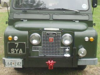
Carmichael Redwing FT/6 CrT Land Rover
 |
There is nothing quite like working on an electrical system without have any sort of electrical diagram.
Fortunately, this is a Land Rover - how complicated can it be?
To begin with, part of the electrical system appears to be original and part was added in at a later date. Also, a few extras were added - front and rear fog lights, reverse lights, a windscreen washer, a 4WD indicator light, directional indicator lights and a Series III combination switch for directions, dimmer and horns. |
||
| Starting point | |||
|
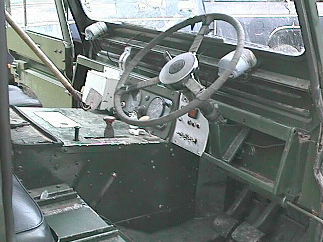
Dashboard layout The white box to the left of the guages contains relays. The silver panel to the right of the guages has switches for the fog and reverse lights, interior lights and windscreen washer. It also has indicators for the directional lights, the fog lights, the reverse lights and 4WD. What you can't see here is the Series III switch on the steering column. |
 |
||
| Click to enlarge | |||
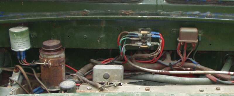 |
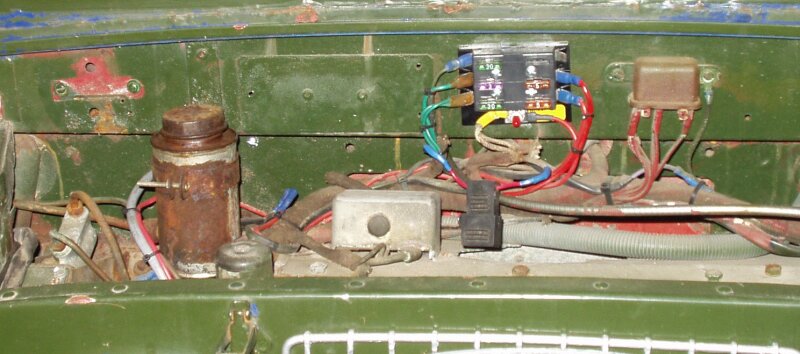
Forward side of the front bulkhead Left to right - Directional flasher relay, brake and clutch fluid resevoir, small round junction block, voltage regulator (for the alternator), main fuseblock, main power relay. I'm guessing that anything with red paint was on this truck when it was in service. That would be the main harness (which is cloth wrapped), the main power relay and fusebox but not the directional relay or the corregated-looking cable conduit. |
||
 |
Behind the drivers seat The engine compartment lid is open in this picture and you can see the original 109 bulkhead. On the left there is a junction box for the light wiring. There is also a similar box by the rear crossmember. From the type of wire I'm guessing it's not what Carmichael installed. Over on the right is the starter button (yes, behind the driver's seat). The little square box was a junction box but is not connected to anything. On the other side of the panel (in the engine compartment) is the ignigtion coil. |
||
| Click to enlarge | |||
|
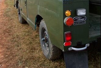
Taillights The yellow directional light is pretty standard, although it is a plastic replacement. I'm not sure about the big red light (running and stop lights). A white reverse light was added on both sides as was the red rear fog lamp (above the reflector). |
 |
||
| Click to enlarge | |||
| Problems? | |||
|
The truck had a few definate problems and a few potential problems. Some things needed to be fixed and some things needed
to be improved on. And, I was going to be adding the search light, blue light and siren so I wanted everything as solid
electrically as possible.
Problems:
Potential problems:
|
|||
| Changes and Additions | |||
| While working on the electrical system I made diagrams and kept notes - which is all going in a notebook. | |||
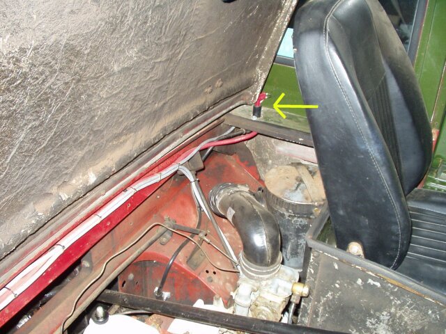 |
Battery Cut-off switch The first addition I made was to install a battery cut-off switch. It is installed in the panel behind the front left seat. The wire from the battery (black wire in this photo) was moved from the starter pushbutton to the cut-off switch and a new red wire was added back to the starter pushbutton. The battery is located under the left side rear seat in the toolbox (the left front seat of a regular 109). |
||
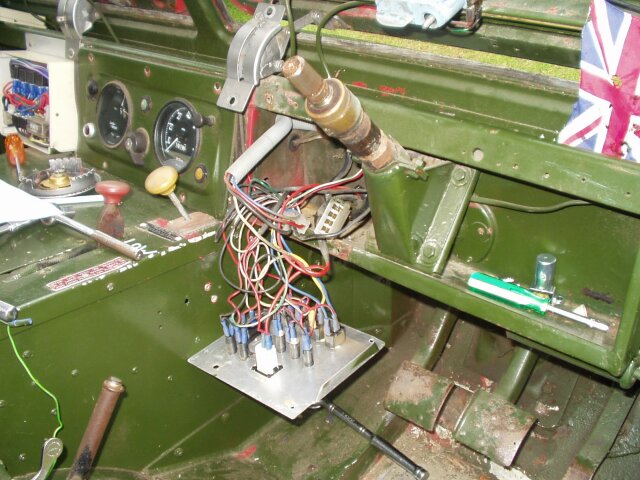 |
Dashboard With the panel dropped and the Series III switch removed. The rectangular plug (just to the left of the steering column) is part of the Series III wiring harness for the directional switch and turned out to a good connection point as I was able to re-use the portion of the harness connected to the switch. |
||
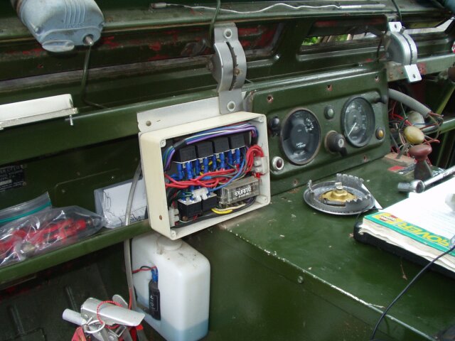 |
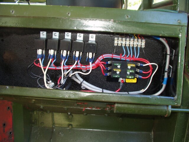
Relay Box Actually, a fairly tidy installation, although if I had to replace a relay I wouldn't be very happy. There are six relays and fuses for the low beams, high beams, front fog lamps, horn, left and right directionals. I was suprised that there was no relay or fuse for the rear fog lamps or reverse lamps. |
||
| Click to enlarge | |||
|
|||
 |
New Main Fuse Panel Mounted in place of the old fuse block. Circuits on the left are the original Land Rover circuits (directionals, cold start and wipers/stoplights/instruments). Circuits on the right are for the front fog lamp relay and the 4WD indicator light. One open position for future use. The lower fuse from the original block (which was not connected to anything) is now handled by a single fuse connector (black) just in case I do find a use for it. |
||
 |
Auxillary Fuse Panel In the panel to the right of the steering column. Also, the headlight dimmer switch, the flasher relay and the relay for the rear fog lamps. All this has to come out when the truck gets re-painted red - I may move the two relays to the front side of the bulkhead. |
||
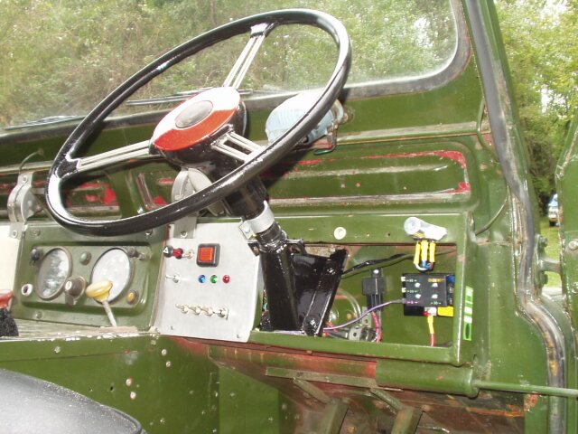 |
Dashboard Slightly improved. The steering wheel was cleaned up and repainted. The correct directional switch mounted and the wiring all neatly tucked away. |
 Click to enlarge
 |
|
| Click to enlarge | |||
| Emergency Equipment Wiring | |||
|
This was fun. I had no idea of how anything was originally wired. The only vestige of the original wiring was a section of
wire in the roof that was for the siren. I was going to install the searchlight, blue beacon light and siren on the roof. I also had a set of two-tone air horns to install on the front crossmember by the radiator and the Winkworth bell on the front bumper. There was also the question of a control panel. But where? The logical place to me was above the windscreen. Easy to reach from either side of the truck and out of the way. Then, there is the question of wiring. The bell and the beacon light draw relatively low current but the other devices need a bit more power. I didn't want to use heavy switches. I decided that relays were needed. I thought that I could install the relays in the engine compartment but I decided to install relays and a fuse panel in the original bulkhead on the right-hand side. A cable runs from the control panel to the relays. Heavy cables run to the devices from the relays. Each circuit has it's own fuse and a sixth fuse is for the control panel and relay coils. I also installed a master switch in the silver panel to the left of the steering column to prevent accidental blowing of horns, etc. |
|||
 |
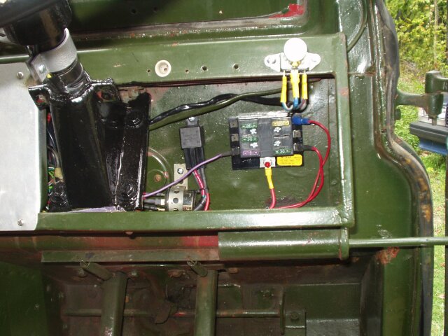
Fuse Panel and Relays In the original bulkhead - right side (behind the driver). Power comes directly from the hot terminal on the starter switch so the fusebox is always live. I need to fabricate a cover for the whole assembly. |
||
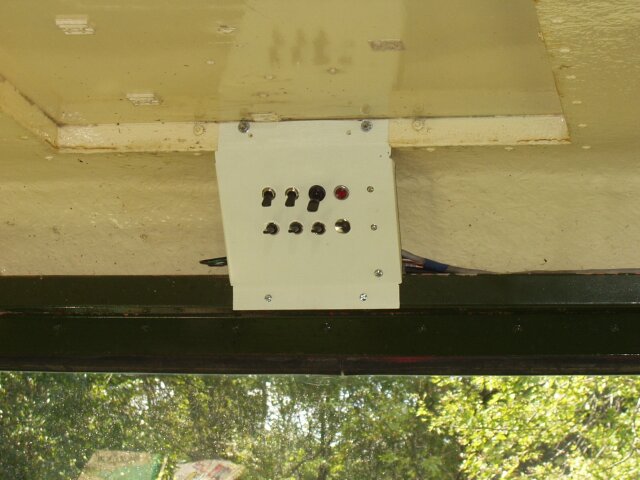 |
Control Panel Switches for the lights, bell, siren and horns. The red indicator shows when the panel is live. The panel needs to be enclosed a bit more. |
||
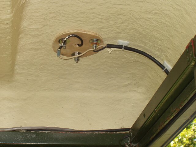 |
Siren mounting The Francis siren is actually mounted using the original holes in the roof. The wood is there for a bit of re-inforcing. |
||
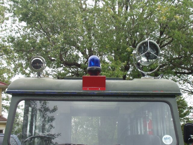 |
Siren, Blue light and searchlight | ||
| Click to enlarge | |||
 |
 |
 |